Thursday, November 7, 2013

BladeRF data around GPS frequency of 1575.42 MHz

My first styled page

GPS revisited and some confessions

The book

An interesting book is:
 "A software defined GPS and Galileo receiver" , a single frequency approach, by Kai Borre et al.
In the back of the book is a CDROM with a dataset. That dataset contains the if-output of a real SDR tuned to a GPS-signal. I copied the test-file to a convenient place and renamed it to testdata.dat.
That started my struggle with GPS. In that timeperiod I did a course on java and wanted to do something ‘useful’ with that knowledge. I decided to build a GPS-receiver and program it in java. So, I bought some books, read a lot about it on the internet and really got a deep understanding of the system and the signals used in a GNSS-system.
I decided to first develop the software and later concentrate on the hardware. The software was difficult enough for me…
To make a really long story short I finally managed to read almanac-data from the GPS-signals. However I got stuck in the tracking loop. I never got the loop stable. That last problem never made it to my blog at http://www.qsl.net/pa1kdg/ by the way.
So, I also did not succeed in calculating the position from the data in that huge data-file. But, what the heck, I learned soo much of that whole project…

Next step

My next step now is restart that whole project with a bladeRF-board. I want to use python now as a programming language. Just because I can ;>))

TANSTAAFL There aint no such thing as a free lunch

Being a retired engineer, the Mathworks, the developers of MATLAB, is no longer interested in me. When I worked at Wageningen University and Research I got an enormous lot of software free. I was addicted to MATLAB (and LABVIEW by the way), with that software you can solve all your scientific problems. After my retirement I soon discovered that the love of the Mathworks I felt was quite different than real life love I perceive on a daily basis from the people around me. Just before retirement I got an SDR-board with a huge Xilinx FPGA. That would be my big and only project after retirement! Nope, Xilinx too discovered I am not longer interesting for them. Real-life for a CEO is about earning money, not about supporting retired engineers. I have not any problem to pay for hardware or software but 2000 bucks for my hobby is in-explainable to my wife (ok, this whole hobby is inexplainable…) OK, I am back on earth now with two feet on the ground, with my bladeRF and open source software. This is my real life now!!

Life is complicated though

On my way along my GPS-project I discovered a lot about linux, VMWare, github, python-eggs, C, VHDL, makefiles, Quartus, SDR-Radio, gnuradio, Octavo and finally plotting in python (and kind of python-MATLAB too). And I found many sidepaths, DesignSpark Mechanical e.g. and soldering SMD’s.

What now

Back to GPS. I want to record a data-file with real-bladeRF-data and try to process that file. First discover what satellites are visible, later read the almanac data. Finally try to get past that data-tracking-loop problem and solve the position-equations. In the meantime I want to try to get some calculations done in the FPGA. It should be possible to do the correlation-part in the FPGA. Quite a challenge!

Some facts

I concentrate on GPS, not GLONASS. GPS transmits on one frequency. All satellites transmit on the same frequency, that is to say, because of Doppler effects there is a slight deviation of that frequency for every satellite. Each satellite has a different code. If you know the code and the Doppler-frequency you can decode the signal of that very satellite. The signal is simply almanac-data at 50 baud. The satellites tell you constantly where they are. Because you know exactly which bit of the code-sequence you receive and because you ‘see’ 4 satelites or more you can calculate where your GPS-antenna is. For 50 $ you can buy a module that does this trick in a very good way, so…

Practical now

Ok, I tune bladeRF to 1575.42 MHz. With a bandwidth of 2 MHz I might expect to get a weak noisy signal, barely a signal, -160dBW. So, only noise.
There are 32 different code sequences. Just try all those sequences one by one.
There are about 60 different frequencies to consider because of the unknown Doppler shift. So try all frequencies.
In a 3D-display one can find some peaks. Then you know some codes and some Doppler shifts. From then on you can decode the satellite signals and get the almanac data. Then you know te distance to each found satellite. In 3D, if you know the distance to 3 or more satellites, you can calculate where you are.  Because you know where the satellites are you know where you are. Simple eh? That is GPS

GLONASS, the Russian system, uses different frequencies. No problem, bladeRF can handle that too. And, with an FPGA you can put the most time-consuming calculations on that chip.

That is the theory.

Tune to 1575.42 MHz. Bandwidth 2 MHz, so samplerate 4 MHz. VGA-gains at 30 dB. Get 1M samples into a file. Perform an FFT. Hopefully something interesting will show up.
Filename A1575.csv without GPSantenna connected and B1575.csv with the GPSantenna connected and pearing out of my window. In the meantime I have a TomTom and a Garmin device locked at the satellites in the sky so I know some data already.

Got my first two files with bladeRF-cli. GPS-systems say: satellites in the sky: 2,4,5,8,9,10,13,16 of which 2,4, 9 are strongest. So I might see satellites 2, 4 and 9 in my datafiles.


[INFO] Using libusb version 1.0.16.10774 [INFO] Found a bladeRF [INFO] Claimed all inferfaces successfully [WARNING] extract_field: Field checksum mismatch [WARNING] Could not extract VCTCXO trim value [WARNING] extract_field: Field checksum mismatch [WARNING] Could not extract FPGA size bladeRF> load fpga hostedx115.rbf Loading fpga from hostedx115.rbf... [INFO] Change to alternate interface 3 [INFO] Change to alternate interface 1 [INFO] Changed into RF link mode: LIBUSB_SUCCESS / LIBUSB_TRANSFER_COMPLETED [INFO] Setting integer sample rate: 1000000 [INFO] Found r value of: 4 [INFO] MSx a + b/c: 316 + 4/5 [INFO] MSx a + b/c: 316 + 4/5 [INFO] MSx P1: 0x00009c66 (40038) P2: 0x00000002 (2) P3: 0x00000005 (5) [INFO] Calculated samplerate: 1000000 + 0/1 [INFO] Set actual integer sample rate: 1000000 [INFO] Setting integer sample rate: 1000000 [INFO] Found r value of: 4 [INFO] MSx a + b/c: 316 + 4/5 [INFO] MSx a + b/c: 316 + 4/5 [INFO] MSx P1: 0x00009c66 (40038) P2: 0x00000002 (2) P3: 0x00000005 (5) [INFO] Calculated samplerate: 1000000 + 0/1 [INFO] Set actual integer sample rate: 1000000 Done. bladeRF> print rxvga1 RXVGA1 Gain: 33 bladeRF> print rxvga2 RXVGA2 Gain: 3dB bladeRF> set rxvga2 33 [WARNING] Setting gain above 30dB? You crazy!! bladeRF> set rxvga2 30 bladeRF> print rxvga2 RXVGA2 Gain: 30dB bladeRF> set bandwidth 2000000 Set RX bandwidth - req: 2000000Hz actual: 2500000Hz Set TX bandwidth - req: 2000000Hz actual: 2500000Hz bladeRF> set frequency 1575420000 Set RX frequency: 1575420000Hz Set TX frequency: 1575420000Hz bladeRF> set bandwidth 2000000 Set RX bandwidth - req: 2000000Hz actual: 2500000Hz Set TX bandwidth - req: 2000000Hz actual: 2500000Hz bladeRF> set samplerate 4000000 [INFO] Setting integer sample rate: 4000000 [INFO] Found r value of: 1 [INFO] MSx a + b/c: 316 + 4/5 [INFO] MSx a + b/c: 316 + 4/5 [INFO] MSx P1: 0x00009c66 (40038) P2: 0x00000002 (2) P3: 0x00000005 (5) [INFO] Calculated samplerate: 4000000 + 0/1 [INFO] Set actual integer sample rate: 4000000 Setting RX sample rate - req: 4000000Hz, actual: 4000000Hz [INFO] Setting integer sample rate: 4000000 [INFO] Found r value of: 1 [INFO] MSx a + b/c: 316 + 4/5 [INFO] MSx a + b/c: 316 + 4/5 [INFO] MSx P1: 0x00009c66 (40038) P2: 0x00000002 (2) P3: 0x00000005 (5) [INFO] Calculated samplerate: 4000000 + 0/1 [INFO] Set actual integer sample rate: 4000000 Setting TX sample rate - req: 4000000Hz, actual: 4000000Hz bladeRF> set bandwidth 2000000 Set RX bandwidth - req: 2000000Hz actual: 2500000Hz Set TX bandwidth - req: 2000000Hz actual: 2500000Hz bladeRF> rx config format=csv n=1000000 file=/temp/A1575.csv bladeRF> rx start bladeRF> rx start bladeRF> rx start bladeRF> rx config format=csv n=1000000 file=/temp/B1575.csv bladeRF> rx start bladeRF> rx start bladeRF> rx start bladeRF>

Note the warning about gain higher than 30 dB ;>))
# FFTSDRdata03.py # Nov-2013 Kees de Groot # # show and analyse snapshot file from bladeRF # remove DC-component # show data in different ways; I/Q, realtimeplot, FFT import pylab as pl import numpy as np import math filename = 'B1575.csv' fsample = 4E6 timestep = 1 / fsample f = open('/Temp/' + filename, 'r') print f print "fsample = ", fsample dataI = [] dataQ = [] n = 0 sumI = 0 sumQ = 0 # read I, Q - values into memory for line in f: list = line.split(',') # two values with comma inbetween Q = int(list[0]) I = int(list[1]) # print 1st 10 lines of data-file if n == 0: print '1st 10 lines of I/Q-values' if n < 10: print I, Q dataI.append(I) # save data in memory dataQ.append(Q) sumI += I sumQ += Q n += 1 averI = sumI / n # calculate average averQ = sumQ / n #averI = 0 # debug #averQ = 0 # debug print "n = ", n # remove DC-component and construct complex dataC dataC = [] for i in range(n): I = dataI[i] - averI Q = dataQ[i] - averQ dataI[i] = I dataQ[i] = Q dataC.append(complex(I,Q)) # this one has complex data pl.figure(1) pl.title("Q versus I of " + filename) pl.xlabel('=======> I') pl.ylabel('=======> Q') pl.plot(dataI, dataQ, 'ro') pl.figure(2) pl.subplot(211) pl.title("I-values of " + filename) pl.ylabel('=======> I') pl.plot(dataI) pl.subplot(212) pl.title("Q-values of " + filename) pl.ylabel('=======> Q') pl.plot(dataQ) pl.figure(3) sp = np.fft.fft(dataC) # use fft, not rfft, since dataC is complex freq = np.fft.fftfreq(n, d=timestep) # for convenient x-axis-ticks pl.title('fft of ' + filename) pl.xlabel('frequency') pl.ylabel('magnitude') pl.plot(freq, abs(sp)/n) # abs converts to magnitude; /n normalizes pl.show()
Run the program for the file without antenna connected: I would expect simply noise but there are three peaks at -583kHz, 0 kHz and 1022 kHz. Perhaps the gain was too big


I would expect simply noise but there are three peaks at
-583kHz, 0 kHz and 1022 kHz.

Now connect GPS-antenna


Perhaps the gain was too big


bladeRF> set rxvga2 27 bladeRF> set rxvga1 27 bladeRF> rx config format=csv n=1000000 file=/temp/C1575.csv bladeRF> rx start bladeRF> rx start bladeRF> rx start bladeRF>


I am still puzzled about the fact that I see a signal when no antenna is connected. I remove the SMB cable from RX and set gains to 0 dB. Then create file D1575.csv:


Biggest peak is at 0 Hz exactly, the other is at 1.01882E6, so around 1 MHz

Again without antenna but a 50 ohm dummyload directly connected to bladeRF-RX-input.
Something went wrong with the board. Error because of physical touching it with too big dummyload directly connected?


[INFO] Using libusb version 1.0.16.10774 [INFO] Found a bladeRF [INFO] Claimed all inferfaces successfully [WARNING] extract_field: Field checksum mismatch [WARNING] Could not extract VCTCXO trim value [WARNING] extract_field: Field checksum mismatch [WARNING] Could not extract FPGA size bladeRF> load fpga hostedx115.rbf Loading fpga from hostedx115.rbf... [INFO] Change to alternate interface 3 [INFO] Change to alternate interface 1 [INFO] Changed into RF link mode: LIBUSB_SUCCESS / LIBUSB_TRANSFER_COMPLETED [INFO] Setting integer sample rate: 1000000 [INFO] Found r value of: 4 [INFO] MSx a + b/c: 316 + 4/5 [INFO] MSx a + b/c: 316 + 4/5 [INFO] MSx P1: 0x00009c66 (40038) P2: 0x00000002 (2) P3: 0x00000005 (5) [INFO] Calculated samplerate: 1000000 + 0/1 [INFO] Set actual integer sample rate: 1000000 [INFO] Setting integer sample rate: 1000000 [INFO] Found r value of: 4 [INFO] MSx a + b/c: 316 + 4/5 [INFO] MSx a + b/c: 316 + 4/5 [INFO] MSx P1: 0x00009c66 (40038) P2: 0x00000002 (2) P3: 0x00000005 (5) [INFO] Calculated samplerate: 1000000 + 0/1 [INFO] Set actual integer sample rate: 1000000 Done. bladeRF> print rxvga1 RXVGA1 Gain: 33 bladeRF> set rxvga1 0 bladeRF> set rxvga2 0 bladeRF> set samplerate 1000000 [INFO] Setting integer sample rate: 1000000 [INFO] Found r value of: 4 [INFO] MSx a + b/c: 316 + 4/5 [INFO] MSx a + b/c: 316 + 4/5 [INFO] MSx P1: 0x00009c66 (40038) P2: 0x00000002 (2) P3: 0x00000005 (5) [INFO] Calculated samplerate: 1000000 + 0/1 [INFO] Set actual integer sample rate: 1000000 Setting RX sample rate - req: 1000000Hz, actual: 1000000Hz [INFO] Setting integer sample rate: 1000000 [INFO] Found r value of: 4 [INFO] MSx a + b/c: 316 + 4/5 [INFO] MSx a + b/c: 316 + 4/5 [INFO] MSx P1: 0x00009c66 (40038) P2: 0x00000002 (2) P3: 0x00000005 (5) [INFO] Calculated samplerate: 1000000 + 0/1 [INFO] Set actual integer sample rate: 1000000 Setting TX sample rate - req: 1000000Hz, actual: 1000000Hz bladeRF> set frequency 1575420000 Set RX frequency: 1575420000Hz Set TX frequency: 1575420000Hz bladeRF> set bandwidth 2000000 Set RX bandwidth - req: 2000000Hz actual: 2500000Hz Set TX bandwidth - req: 2000000Hz actual: 2500000Hz bladeRF> rx config format=csv n=1000000 file=/temp/E1575.csv bladeRF> start Unrecognized command: start bladeRF> rx start bladeRF> rx start Error: Operation invalid in current state bladeRF> rx start bladeRF> rx start bladeRF> rx start bladeRF>
Beware: sample rate = 1 Mhz


One peak at zero Hz, the other is at 19.354 Hz.
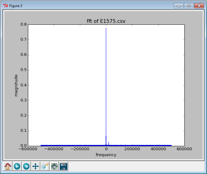
Now samplerate = 2 MHz


Now same with samplerate = 4MHz


Still, no antenna connected, but dummyload directly at RX

Conclusion

I have a problem. I expected a flat noise floor without any antenna connected. But I see some spurious signals. I might be able to explain the signal at 0 Hz. But the others are strange.
I have to check again without any antenna connected and vary the parameters that I can set:
n, the number of samples, it might be a hickup of the interface
samplerate, there is a clock, so there are some signals
frequency, mixer-products?
rxvga1 the more gain, the more spurious signals
rxvga2 same
bandwidth, dont think so

Well I had a nice evening trying to get a GPS-satellite-signal but discovered my bladeRF also is very creative?


Monday, November 4, 2013

Data analysis of a file of bladeRF samples with python

My first styled page

Finally, some python-programming

With bladeRF-CLI, the bladeRF-control-program, one can collect received data into a file. That file contains I- and Q-samples. With a very simple python-program I try to get some insight in the received data.

First python-program for bladeRF-datafile

Create a data-file with bladeRF-cli:
bladeRF> version [WARNING] FPGA currently does not have a version number. Serial #: b436de8c8212b9aeaaeba852246866e7 VCTCXO DAC calibration: 0x9a5d FPGA size: 115 KLE Firmware version: 1.5 FPGA version: 0.0 bladeRF> print bandwidth RX Bandwidth: 28000000Hz TX Bandwidth: 28000000Hz bladeRF> print samplerate [INFO] Calculated samplerate: 1000000 + 0/1 [INFO] Calculated samplerate: 1000000 + 0/1 RX sample rate: 1000000 TX sample rate: 1000000 bladeRF> set frequency 800000000 Set RX frequency: 800000000Hz Set TX frequency: 800000000Hz bladeRF> rx config format=csv n=1024 file=C:/temp/A800MHzCW.csv bladeRF> rx start bladeRF>
And now analyse the datafile with a python-program

f = open('/Temp/A800MHzCW.csv', 'r') n = 0 averageI = 0 averageQ = 0 for line in f: if n < 10: print line, list = line.split(',') I = int(list[0]) Q = int(list[1]) #print "I =",I, "Q =",Q averageI = averageI + I averageQ = averageQ + Q n = n + 1 averageI = averageI / n averageQ = averageQ / n print f print "averageI = ", averageI, " averageQ = ", averageQ
and the output is:
Python 2.7.3 (default, Apr 10 2012, 23:31:26) [MSC v.1500 32 bit (Intel)] on win32
Type "copyright", "credits" or "license()" for more information.
>>> ================================ RESTART ================================
>>> 
110, 100
113, 100
112, 103
114, 104
112, 105
110, 101
114, 100
112, 100
115, 97
113, 97

averageI =  110  averageQ =  98
>>>

This may seem a silly simple program but:

  • I can read a file
  • I can interpret the content and get I and Q samples
  • I can print values
  • I can calculate some data
So, this is a sort of 'Hello world' program.

Plotting in python

How?
I need to install matplotlib for python 2.7
Download from http://sourceforge.net/projects/matplotlib/postdownload?source=dlp
And execute matplotlib-1.3.1.win-amd64-py2.7.exe


Helloo, I _have_ python 2.7 installed!!!

I have python 2.7 running on my machine, obviously not registered properly?
I’’ try matplotlib-1.3.1.win32-py2.7.exe instead


Seems to be ok.

But...


So...


From http://www.lfd.uci.edu/~gohlke/pythonlibs/
python-dateutil-1.5.win32-py2.7.exe

>>> import matplotlib

Traceback (most recent call last):
  File "<pyshell#4>", line 1, in <module>
    import matplotlib
  File "C:\Python27\lib\site-packages\matplotlib\__init__.py", line 125, in <module>
    raise ImportError("matplotlib requires pyparsing")
ImportError: matplotlib requires pyparsing
>>>

From http://www.lfd.uci.edu/~gohlke/pythonlibs/
pyparsing-2.0.1.win32-py2.7.exe

>>> import matplotlib
>>>

Quite encouraging!

All examples from internet about plotting with matplotlib function very well!

Nice playing by the way!!

Sometimes it is difficult to go persistently only into the direction of your goal. Before my retirement I had to focus on result, that was very important. But there are so many distracting sidepaths... Nowadays I play a lot, go into an enormous lot of sidepaths, and that is great fun! So, progress is not the issue anymore...

Some data-files

summary:
freq = 1575.450.000 Hz
bandwidth = 28.000.000 Hz
samplerate = 1.000.000 Hz
file=/temp/AA.csv
n = 5000 samples

# FFTSDRdata01.py # Oct-2013 Kees de Groot # # show data collected from bladeRF import pylab as pl import numpy as np import math filename = 'AA.csv' f = open('/Temp/' + filename, 'r') print f n = 0 dataI = [] dataQ = [] dataC = [] for line in f: # print 1st 10 lines of data-file if n < 10: print line, list = line.split(',') I = int(list[0]) Q = int(list[1]) dataI.append(I) dataQ.append(Q) dataC.append(complex(I,Q)) n += 1 print "n = ", n pl.figure(1) pl.title("Q versus I of " + filename) pl.xlabel('=======> I') pl.ylabel('=======> Q') pl.plot(dataI, dataQ, 'ro') pl.figure(2) pl.subplot(211) pl.title(filename) pl.ylabel('=======> I') pl.plot(dataI) pl.title("I-values of " + filename) pl.subplot(212) pl.title(filename) pl.ylabel('=======> Q') pl.plot(dataQ) pl.figure(3) fsample = 1E6 timestep = 1 / fsample sp = np.fft.fft(dataC) freq = np.fft.fftfreq(n, d=timestep) pl.title(filename) pl.plot(freq, abs(sp)) pl.show()


Python 2.7.3 (default, Apr 10 2012, 23:31:26) [MSC v.1500 32 bit (Intel)] on win32
Type "copyright", "credits" or "license()" for more information.
>>> ================================ RESTART ================================
>>>
<open file '/Temp/AA.csv', mode 'r' at 0x0343D390>
80, 80
82, 77
81, 77
77, 79
80, 77
80, 81
78, 79
81, 76
84, 80
80, 76
n =  5000


No rocket-science, but quite encouraging.
I see some interruptions/setting-changes/discontinuities, but what-the-heck: nice pictures!
(I may be a strange person, but I really became quite excited when I first got these pictures!)

Settable gains inside the bladeRF-board

From the log of SDR-Radio console:

16:33:51> bladeRF
16:33:51>     --Starting sending
16:33:51>     Set RX VGA gain 2: value 30dB, status = Success
16:33:51>     Set RX LPF mode: Normal, status = Success
16:33:51>     Set RX VGA gain 1: value 30dB, status = Success
16:33:51>     Set LNA gain: Maximum, status = Success
16:33:51> Input Reader (Part 1)
16:33:51>     Starting listener, Radio defn 04A686B0, buffer size 65536

There is a third settable gain: lna-gain.


[INFO] Using libusb version 1.0.16.10774 [INFO] Found a bladeRF [INFO] Claimed all inferfaces successfully [INFO] Change to alternate interface 1 [INFO] Changed into RF link mode: LIBUSB_SUCCESS / LIBUSB_TRANSFER_COMPLETED [WARNING] extract_field: Field checksum mismatch [WARNING] Could not extract VCTCXO trim value [WARNING] extract_field: Field checksum mismatch [WARNING] Could not extract FPGA size bladeRF> print bandwidth RX Bandwidth: 28000000Hz TX Bandwidth: 28000000Hz bladeRF> print frequency RX Frequency: 1575450000Hz TX Frequency: 1575450000Hz bladeRF> print samplerate [INFO] Calculated samplerate: 38400000 + 0/1 [INFO] Calculated samplerate: 1000000 + 0/1 RX sample rate: 38400000 TX sample rate: 1000000 bladeRF> print vga1gain print: Invalid parameter (vga1gain) bladeRF> print gainvga1 print: Invalid parameter (gainvga1) bladeRF> help set set The set command takes a parameter and an arbitrary number of arguments for that particular command. The parameter is one of: bandwidth Bandwidth settings config Overview of everything frequency Frequency settings lmsregs LMS6002D register dump loopback Loopback settings mimo MIMO settings pa PA settings pps PPS settings refclk Reference clock settings rxvga1 Gain setting of RXVGA1 in dB (range: ) rxvga2 Gain setting of RXVGA2 in dB (range: ) samplerate Samplerate settings trimdac VCTCXO Trim DAC settings txvga1 Gain setting of TXVGA1 in dB (range: ) txvga2 Gain setting of TXVGA2 in dB (range: ) bladeRF> print rxvga1 RXVGA1 Gain: 30 bladeRF> print rxvga2 RXVGA2 Gain: 30dB bladeRF>
nope, no other gain-setting.
What is the maximum data-rate / samplerate for USB2?

A lot of different experiments lead to the following python-program:

A.csv is a file without any connection from bladeRF to the signal generator, so, pure noise

The python-program:

# FFTSDRdata03.py # Nov-2013 Kees de Groot # # show and analyse snapshot file from bladeRF # remove DC-component # show data in different ways; I/Q, realtimeplot, FFT import pylab as pl import numpy as np import math filename = 'A.csv' fsample = 1E6 timestep = 1 / fsample f = open('/Temp/' + filename, 'r') print f print "fsample = ", fsample dataI = [] dataQ = [] n = 0 sumI = 0 sumQ = 0 # read I, Q - values into memory for line in f: list = line.split(',') # two values with comma inbetween Q = int(list[0]) I = int(list[1]) # print 1st 10 lines of data-file if n == 0: print '1st 10 lines of I/Q-values' if n < 10: print I, Q dataI.append(I) # save data in memory dataQ.append(Q) sumI += I sumQ += Q n += 1 averI = sumI / n # calculate average averQ = sumQ / n print "n = ", n # remove DC-component and construct complex dataC dataC = [] for i in range(n): I = dataI[i] - averI Q = dataQ[i] - averQ dataI[i] = I dataQ[i] = Q dataC.append(complex(I,Q)) # this one has complex data pl.figure(1) pl.title("Q versus I of " + filename) pl.xlabel('=======> I') pl.ylabel('=======> Q') pl.plot(dataI, dataQ, 'ro') pl.figure(2) pl.subplot(211) pl.title("I-values of " + filename) pl.ylabel('=======> I') pl.plot(dataI) pl.subplot(212) pl.title("Q-values of " + filename) pl.ylabel('=======> Q') pl.plot(dataQ) pl.figure(3) sp = np.fft.fft(dataC) # use fft, not rfft, since dataC is complex freq = np.fft.fftfreq(n, d=timestep) # for convenient x-axis-ticks pl.title('fft of ' + filename) pl.xlabel('frequency') pl.ylabel('magnitude') pl.plot(freq, abs(sp)/n) # abs converts to magnitude; /n normalizes pl.show()
With output
A.csv is a file without any connection from bladeRF to the signal generator, so, pure noise:


There is an enormous peak at 200kHz which was not there before on other pictures. I have to find out what is happening there.

I did a lot of more measurements:

BladeRF is setup:
RX Bandwidth:  28.000.000Hz
RX sample rate: 1.000.000
RX frequency:  646.000.000 Hz
RXVGA1 Gain:  33
RXVGA2 Gain:   3dB
A.csv is a file without any connection from bladeRF to the signal generator, so, pure noise
Now the signal generator, a HP8656B is directly connected to RX of bladeRF
B.csv is 646 MHz, AM 1 kHz 75% modulation, 1 µV amplitude
C.csv is 3,98 µV
D.csv is 7.94 µV
E.csv is 31.6 µV
F.csv is 63,1 µV

Back to 1 µV and now FM 1 kHz sweep 75 kHz wide

AF.csv is 1 µV
BF.csv is 3.98 µV
CF.csv is 7.94 µV
DF.csv is 31,6 µV

This last signal, DF.csv, is very nice:


Conclusion

I managed to get a file with data (I and Q-samples) from bladeRF-board. With a program written in python I managed to read these files, interpret and show the data. Nice results, and a big question: what is that signal at 200kHz? So, every experiment gives you new things to investigate...

Wife: what are you doing?
Me: Well, you know, my project..
Wife: What are you trying to achieve?
Me: Well, at the end this board will tell me where I am..
Wife: Do you know where you are at the end?
Me: Yes..
Wife: So, ???

This whole project, that keeps me out of all evil places of the world, that keeps me home, ok, that keeps me behind my laptop the whole evening and the first part of the night, that keeps me active,
h o w  c a n  I  e v e r  e x p l a i n  t o  a n  a l i e n  w h a t  I  a m  d o i n g  h e r e?
My wife stops asking when I speak the magic spell: "it is just my hobby!"


Friday, November 1, 2013

How to blow up a bladeRF-board and recover from it

My first styled page In the blog of nuand.com I read:
By upgrading to the latest FX3 image ( http://nuand.com/fx3/latest.img ) you can now store FPGA images on the SPI flash by running `bladeRF-cli -L hostedx40.rbf`. This will allow your bladeRF to read an FPGA image from flash and program the FPGA without the need of a host computer.
So, that is what I tried. But -L is not the right command, nothing happens. So, I tried -f instead. I programmed the Flash-memory of the USB-FX3-chip with an FPGA-image. Yes, very stupid. After that I had an expensive board not even useful as a presse-papier.

But don't panic. I easily found an followed the recipe to wake up my precious bladeRF-board from the "booting-sleep" it was in.

How I destroyed the Flash-memory

Microsoft Windows [versie 6.1.7601] Copyright (c) 2009 Microsoft Corporation. Alle rechten voorbehouden. C:\Users\lonneke\Desktop>cd \Program Files (x86)\bladeRF\x64 C:\Program Files (x86)\bladeRF\x64>bladeRF-cli -L hostedx115.rbf 0.5.0-git- C:\Program Files (x86)\bladeRF\x64>bladeRF-cli Usage: bladeRF-cli bladeRF command line interface and test utility (0.4.0-git-) Options: -d, --device Use the specified bladeRF device. -f, --flash-firmware Flash specified firmware file. -l, --load-fpga Load specified FPGA bitstream. -p, --probe Probe for devices, print results, then exit. -s, --script Run provided script. -i, --interactive Enter interactive mode. -L, --lib-version Print libbladeRF version and exit. -v, --verbosity Set the libbladeRF verbosity level. Levels, listed in increasing verbosity, are: critical, error, warning, info, debug, verbose -V, --version Print CLI version and exit. -h, --help Show this help text. Notes: The -d option takes a device specifier string. See the bladerf_open() documentation for more information about the format of this string. If the -d parameter is not provided, the first available device will be used for the provided command, or will be opened prior to entering interactive mode. C:\Program Files (x86)\bladeRF\x64>bladeRF-cli.exe -f ../hostedx115.rbf [INFO] Using libusb version 1.0.16.10774 [INFO] Found a bladeRF [INFO] Claimed all inferfaces successfully [INFO] Change to alternate interface 1 [INFO] Changed into RF link mode: LIBUSB_SUCCESS / LIBUSB_TRANSFER_COMPLETED Flashing firmware... [INFO] Change to alternate interface 2 [INFO] Erasing 55 sectors starting @ sector 0 [INFO] Erased sector 0... [INFO] Erased sector 1... [INFO] Erased sector 2... [INFO] Erased sector 3... [INFO] Erased sector 4... [INFO] Erased sector 5... [INFO] Erased sector 6... [INFO] Erased sector 7... [INFO] Erased sector 8... [INFO] Erased sector 9... [INFO] Erased sector 10... [INFO] Erased sector 11... [INFO] Erased sector 12... [INFO] Erased sector 13... [INFO] Erased sector 14... [INFO] Erased sector 15... [INFO] Erased sector 16... [INFO] Erased sector 17... [INFO] Erased sector 18... [INFO] Erased sector 19... [INFO] Erased sector 20... [INFO] Erased sector 21... [INFO] Erased sector 22... [INFO] Erased sector 23... [INFO] Erased sector 24... [INFO] Erased sector 25... [INFO] Erased sector 26... [INFO] Erased sector 27... [INFO] Erased sector 28... [INFO] Erased sector 29... [INFO] Erased sector 30... [INFO] Erased sector 31... [INFO] Erased sector 32... [INFO] Erased sector 33... [INFO] Erased sector 34... [INFO] Erased sector 35... [INFO] Erased sector 36... [INFO] Erased sector 37... [INFO] Erased sector 38... [INFO] Erased sector 39... [INFO] Erased sector 40... [INFO] Erased sector 41... [INFO] Erased sector 42... [INFO] Erased sector 43... [INFO] Erased sector 44... [INFO] Erased sector 45... [INFO] Erased sector 46... [INFO] Erased sector 47... [INFO] Erased sector 48... [INFO] Erased sector 49... [INFO] Erased sector 50... [INFO] Erased sector 51... [INFO] Erased sector 52... [INFO] Erased sector 53... [INFO] Erased sector 54... [INFO] Change to alternate interface 2 [INFO] Flashing with write size = 64 [INFO] Verifying with read size = 64 Done. C:\Program Files (x86)\bladeRF\x64>bladeRF-cli -i [INFO] Using libusb version 1.0.16.10774 [ERROR] Couldn't populate devinfo - LIBUSB_ERROR_NOT_SUPPORTED [ERROR] Could not open FX3 bootloader device: LIBUSB_ERROR_NOT_SUPPORTED [ERROR] No devices available on the libusb backend. Failed to open device (NULL): No devices available Could not open device bladeRF> exit C:\Program Files (x86)\bladeRF\x64>bladeRF-cli.exe -f ../latest.img [INFO] Using libusb version 1.0.16.10774 [ERROR] Couldn't populate devinfo - LIBUSB_ERROR_NOT_SUPPORTED [ERROR] Could not open FX3 bootloader device: LIBUSB_ERROR_NOT_SUPPORTED [ERROR] No devices available on the libusb backend. Failed to open device (NULL): No devices available Could not open device C:\Program Files (x86)\bladeRF\x64>
Something is very wrong. I programmed the Flash-memory with a completely nonsense FPGA-image. This is not a non-sense image but not code that can be executed by the FX3-chip. The FPGA-code is intended for the setup-configuration for the FPGA.

What now?

Take a break, have a coffee, keep calm and count your blessings...
Then, google and find the solution.
I have to use a Cypress tool to flash the right image back on the bladeRF-board


There is not any sign of a libusb-bladeRF-board...


BladeRF is not there… (but physically connected to a USB2-port.


Nuand has a tool!
Let’s try the rescue flasher…


Very short flash of a command-window, but:

Nope


As you can see, I am not trying to show how smart I am, neither how stupid I am. I just want to show what I tried in a situation like this.

Laptop restarted, bladeRF in USB2-port


Nothing yet.
Now trying to re-install bladeRF-CLI using Windows-installer, hoping to re-flash automagically??

Encouraging…


Nothing yet,
Replug bladeRF

Ah, stupid me, it was plugged in an USB3-port instead of USB2.

Try again


Nope


This is the USB Control Center of Cypress.
Beware: there are versions for FX2 and FX3. 
We need the latter, FX3


I could not show what happens here. Normally I press
<Ctrl><Alt><PrtScrn> to get a pastable image. While
doing that, the info simply disappeared. 

Programmed FX3, pointed to latest.img


YES!!! there it is: libusbK USB Devices


And bladeRF as seen by bladeRF-CLI
Only thing is load hostedx115.rbf


Microsoft Windows [versie 6.1.7601] Copyright (c) 2009 Microsoft Corporation. Alle rechten voorbehouden. C:\Users\lonneke\Desktop>cd C:\Program Files (x86)\bladeRF C:\Program Files (x86)\bladeRF>bladerf_winflasher The device is running the FX3 bootloader. Please use the Cypress Control tool to flash the SPI C:\Program Files (x86)\bladeRF>bladerf-cli -i [INFO] Using libusb version 1.0.16.10774 [INFO] Found a bladeRF [INFO] Claimed all inferfaces successfully [WARNING] extract_field: Field checksum mismatch [WARNING] Could not extract VCTCXO trim value [WARNING] extract_field: Field checksum mismatch [WARNING] Could not extract FPGA size bladeRF> load fpga hostedx115.rbf Loading fpga from hostedx115.rbf... [INFO] Change to alternate interface 3 [INFO] Change to alternate interface 1 [INFO] Changed into RF link mode: LIBUSB_SUCCESS / LIBUSB_TRANSFER_COMPLETED [INFO] Setting integer sample rate: 1000000 [INFO] Found r value of: 4 [INFO] MSx a + b/c: 316 + 4/5 [INFO] MSx a + b/c: 316 + 4/5 [INFO] MSx P1: 0x00009c66 (40038) P2: 0x00000002 (2) P3: 0x00000005 (5) [INFO] Calculated samplerate: 1000000 + 0/1 [INFO] Set actual integer sample rate: 1000000 [INFO] Setting integer sample rate: 1000000 [INFO] Found r value of: 4 [INFO] MSx a + b/c: 316 + 4/5 [INFO] MSx a + b/c: 316 + 4/5 [INFO] MSx P1: 0x00009c66 (40038) P2: 0x00000002 (2) P3: 0x00000005 (5) [INFO] Calculated samplerate: 1000000 + 0/1 [INFO] Set actual integer sample rate: 1000000 Done. bladeRF>
Yes, everything ok!

Epilogue

I blew up and repaired my precious bladeRF-board. Later that evening I read something about SDR-radio.com. That is hot stuff!!

Playing with a signal-generator at a frequency adjacent to a tv-channel.

I simply put a whip-antenna on the signal-generator, a HP 8656B signal generator 0.1-990 MHz


What a marvelous piece of software! I played hours with it. First connected a signal genarator, later my active GPS-antenna and still later a 70 cm antenna on the roof. Yes, it was very late that evening. I managed to write some python-software to decode the bladeRF-outputfiles. Plots and FFTs. Later more. 

Saturday, October 26, 2013

A case for bladeRF and DesignSpark Mechanical

A case for DesignSparc Mechanical

The bladeRF-board was bought for GNSS-experiments. So I need to connect a GPS-antenna. The one I have is an active antenna that needs power. I built a small circuit to feed the antenna using phantom power. From two small pieces of PCB I made a stand and soldered them on a PCB-ground plate. This became the basis of my bladeRF-case.

I did some drawing with DesignSpark Mechanical and was looking for some serious work to develop skills: a case was born...

First sketch


The GPS-antenna is a Unictron GPS 02 and needs 2.4 .. 5,5 V. At 5 V it draws about 20 mA current. Not too much for the 5 V regulator in the bladeRF-board. I placed a jumper  on J70 and soldered a wire to get the needed 5 V for the antenna-supply. 

In UHF the golden rule is: the smaller the better. I decided to use SMD only. From my (big) SMD-junkbox I found the needed parts. The values are not calculated: I just more or less took what I found in the junkbox...

In retrospect the value of 39 ohm for the series resistor might become a problem. The power dissipation I*I*R = 20 * 20 * 39 = 15.6 mW. This SMD is very small, about 1*2 mm. I have no idea how much it can dissipate.

In case of a short cut the dissipation will be U*U/R = 5 *5 / 39 = 0,6 W. The resistor will act as a fuse in that case!

The RX-enty of the bladeRF is protected by two anti-parallel-diodes, hence the 820 pF capacitor to the RX-entry.

Connectors

I bought an SMB socket and a socket for the GPS-antenna, I think is was MMX with a diameter of 3.2 mm. Quite expensive: 6 + 10 euro at my local electronics-store. I needed some support for this sockets so decided to use a piece of PCB. Drilling an soldering of PCB makes a nice and sturdy support.


In the picture above you see a PCB ground plane and the support stand for the connectors. In the air between the two connectors you see the SMD- 820 pF capacitor. The red wire is the +5 V wire connecting to a jumper on J70 nof the bladeRF.
In the upper right you see that the bolt that holds the bladeRF is soldered to the base-plate.

Warning

For the sockets you need to drill a hole of 6.5 mm. I was so stupid to hold the small piece of PCB with my fingers firmly pressed to the table while drilling the 6.5 mm hole in the PCB. You might guess what happened: the PCB will be lifted up by the drill and will turn around the drill. With your fingers so close-by you get a nice long (15 mm) wound and rather deep too.

OK, not love and understanding this time, but my wife helped me close the wound with a nice plaster. Yes, I am 65 and stupid too!

The SMD-circuit in 3D


I used DesignSpark Mechanical to draw the circuit (just for fun). 

The same, but now in real-life:


The case

The case is a lower case and an upper case (my name, by the way is Kees which is pronounced like case, just in case). The lower case is a piece of PCB. At Elektor's shop I bought a "project-case". This is not much more than two pieces of plastic with some hex-stands. I used one plate of the project-case as the top plate. 


The bladeRF board is mounted with 4 bolts 2.5 mm. The bolts are soldered on the bottom-plate. The holes in the bladeRF-board are not 3 mm, just slightly smaller. That is a pity because M3 is much stronger than M2.5 that I had to use.

Epilogue

It was nice, after a long time of only programming, to find myself with a soldering iron again. It was great fun to solder the tiny SMD-parts, this time without a microscope. I found spectacles with very thick glasses +3. Sometimes I wear two spectacles for a better view (I am not joking, try it yourself!).

PCB is a very good material to make a housing, a case, for your circuits.

DesignSpark Mechanical is a free tool. Download it free and use it. I thought it is only a package to use a pre defined library of connectors from RS, but it is more, much more than that!


Next time, my ramblings with DesignSpark Mechanics or my struggling with getting GNSS-bladeRF-samples into a file and processing that file with Python.

Feel free to comment if something is not soo obvious!


Wednesday, October 23, 2013

The Windows installer for bladeRF-software

Nuand has new installer software for Windows

In the blog at nuand.com they write:
There is now a Windows based installer for the bladeRF that will install all of the relevant drivers, user mode utilities, and FX3/FPGA images. The file can be directly downloaded from http://nuand.com/downloads/bladerf_win_installer.exe .
OK, download this installer and open it


A warning, but what else can I do than execute this file?


Yes! There is bladeRF CLI in the Windows Start Menu

What about USB3?


The bladeRF-board was connected all the time at anUSB2-port. Now the LEDs stopped blinking. The installation did something to it. The bladeRF-board was connected all the time at a USB2-port. I’ll unplug it and reconnect to a USB3-port and start bladeRF CLI


Oeps, the board is invisible for bladeRF-cli when connected at a USB3-port!
Reconnect to a USB2-port and restart bladeRF CLI


Get the latest image for the FPGA


I have to get the latest.img from http://nuand.com/fx3/latest.img
C:\bladeRF-master_new might be a good place for it.
I’ll put it on C:\Program Files (x86)\bladeRF

A lot of errors, I seem to have to define a variable


I get a lot of errors and I have to define an environment variable in Windows.
So, in the configuration screen of the start menu of Windows I select advanced and environment-variables.

Defined BLADERF_SKIP_FW_SIZE_CHECK = 0

Now it seems to be OK


Connect an antenna and try to get samples into a file


Oh boy, this is interesting. It is late in the night already but I take the antenna from my Kenwood  TH-F7, it has the same connector as the bladeRF-board, and connect it to RX.


I created a file with samples. What is in this comma-separated-values file?

File  C:/temp/new282810M.csv reads:

…
89, 81
88, 80
92, 76
84, 76
90, 77
88, 76
92, 77
90, 84
85, 77
92, 80
88, 81
86, 75
92, 73
86, 82
91, 76
89, 81
91, 77
92, 77
88, 81
86, 73
88, 77
86, 77
90, 77
90, 77
91, 77
88, 77
91, 79

…
So, not so interesting. I’d expect more variation in the value of the numbers…

Epilogue

OK, installation of the Windows software with the installer from Nuand is a breeze! Thanks a lot for all their efforts. They keep doing a great job.

After installation I got error-messages with a clue: define BLADERF_SKIP_FW_SIZE_CHECK = 0

It seems I did only get some noise in the file with the samples. I'll experiment with some parameters like the gain, bandwidth, frequency and samplerate. I have a signal-generator that can put a signal up to 1 GHz on the antenna. With 100 W output-power to the RX-input of the bladeRF-board I should be able to get some smoke into and out of my file!

(dont try this with 100 W, some microVolts should be enough :>))


Sunday, October 13, 2013

Architecture of the bladeRF-software

Thoughts

Before I bought the bladeRF-board I decided to make a program coded in python to control my bladeRF-board from the laptop. Furthermore I wanted to do the time-consuming calculations on the FPGA coded in VHDL. Quite challenging. Now I understand more of the bladeRF. There is a very good program bladeRF-cli that can do almost everything I want. There is C-coded program in the FX3-USB-chip. And there seems to be a NIOS-processor soft-programmed in the FPGA. That can be programmed in C too?

Goal

To understand/learn a device I define a goal and try to achieve that goal:

 "Try to code a python-program that gets some info from the bladeRF, eg. the bandwidth".

 Investigating the bladeRF-software

On my laptop the software is at C:\bladeRF-master.

Have a look at the source bladeRF.cli

The source for the basic funtions of bladeRF seems to be at

C:\bladeRF-master\host\libraries\libbladeRF\src

Doc for the libusb-API

I was desperately looking for the python-libusb-API on the internet. I did not find it!! However, the doc is in python itself, just type “help(usb)” and you get:

Help on package usb:

NAME
    usb - PyUSB - Easy USB access in Python

FILE
    c:\python27\lib\site-packages\usb\__init__.py

DESCRIPTION
    This package exports the following modules and subpackages:
    
        core - the main USB implementation
        legacy - the compatibility layer with 0.x version
        backend - the support for backend implementations.
    
    Since version 1.0, main PyUSB implementation lives in the 'usb.core'
    module. New applications are encouraged to use it.

PACKAGE CONTENTS
    _debug
    _interop
    backend (package)
    control
    core
    legacy
    util

DATA
    __all__ = ['legacy', 'core', 'backend', 'util']
    __author__ = 'Wander Lairson Costa'

AUTHOR
    Wander Lairson Costa


>>> Help(usb.core):

Help on module usb.core in usb:
NAME
    usb.core - usb.core - Core USB features.

FILE
    c:\python27\lib\site-packages\usb\core.py

DESCRIPTION
    This module exports:
    
    Device - a class representing a USB device.
    Configuration - a class representing a configuration descriptor.
    Interface - a class representing an interface descriptor.
    Endpoint - a class representing an endpoint descriptor.
    find() - a function to find USB devices.

CLASSES
    __builtin__.object
        Configuration
        Device
        Endpoint
        Interface
Etcetera, so the doc is in python!!

My goal again

In order to set the bandwidth to 12.345 MHz what to program in python? After that, read back the bandwidth from bladeRF-cli.

bladeRF-software

C:\bladeRF-master\host\libraries\libbladeRF\src contains bladerf.c:

….
int bladerf_get_bandwidth(struct bladerf *dev, bladerf_module module,
                            unsigned int *bandwidth )
{
    /* TODO: Make return values for lms call and return it for failure */
    lms_bw_t bw = lms_get_bandwidth( dev, module );
    *bandwidth = lms_bw2uint(bw);
    return 0;
}
….


C:\bladeRF-master\host\libraries\libbladeRF\src contains lms.c:

…
// Get the bandwidth for the selected module
lms_bw_t lms_get_bandwidth(struct bladerf *dev, bladerf_module mod)
{
    uint8_t data;
    uint8_t reg = (mod == BLADERF_MODULE_RX) ? 0x54 : 0x34;
    bladerf_lms_read(dev, reg, &data);
    data &= 0x3c;
    data >>= 2;
    return (lms_bw_t)data;
}
…
So, search for bladerf_lms_read.

C:\bladeRF-master\host\libraries\libbladeRF\include

libbladeRF.h contains:

/**
 * Read a LMS register
 *
 * @param   dev         Device handle
 * @param   address     LMS register offset

 * @param   val         Pointer to variable the data should be read into
 *
 * @return 0 on success, value from \ref RETCODES list on failure
 */
API_EXPORT int bladerf_lms_read(struct bladerf *dev,
                                uint8_t address,
                                uint8_t *val);

/**
 * Write a LMS register
 *
 * @param   dev         Device handle
 * @param   address     LMS register offset
 * @param   val         Data to write to register
 *
 * @return 0 on success, value from \ref RETCODES list on failure
 */
API_EXPORT int bladerf_lms_write(struct bladerf *dev,
                                 uint8_t address,
                                 uint8_t val);


What is API_EXPORT? a macro?


…
 /** Marks an API routine to be made visible to dynamic loader  */
#if defined _WIN32 || defined _CYGWIN__
#   ifdef __GNUC__
#       define API_EXPORT __attribute__ ((dllexport))
#   else
#       define API_EXPORT __declspec(dllexport)
#   endif
#else
#   define API_EXPORT __attribute__ ((visibility ("default")))
#endif

…

Search for lms_read and lms_write


C:\bladeRF-master\host\libraries\libbladeRF\src
bladerf.c


/*------------------------------------------------------------------------------
 * LMS register read / write functions
 *----------------------------------------------------------------------------*/

int bladerf_lms_read(struct bladerf *dev, uint8_t address, uint8_t *val)
{
    return dev->fn->lms_read(dev,address,val);
}

int bladerf_lms_write(struct bladerf *dev, uint8_t address, uint8_t val)
{
    return dev->fn->lms_write(dev,address,val);
}

C:\bladeRF-master\host\libraries\libbladeRF\src bladerf_priv.h

   /* LMS6002D accessors */
    int (*lms_write)(struct bladerf *dev, uint8_t addr, uint8_t data);
    int (*lms_read)(struct bladerf *dev, uint8_t addr, uint8_t *data);


Where are lms_read and lms_write defined?


C:\bladeRF-master\hdl\fpga\ip\altera\nios_system\software\lms_spi_controller hello_world_small.c

#define LMS_READ  0
#define LMS_WRITE  (1<<7 data-blogger-escaped-access="" data-blogger-escaped-address="" data-blogger-escaped-an="" data-blogger-escaped-backend="(struct" data-blogger-escaped-bladerf-master="" data-blogger-escaped-bladerf="" data-blogger-escaped-bladerf_linux="" data-blogger-escaped-c:="" data-blogger-escaped-definition="" data-blogger-escaped-dev-="" data-blogger-escaped-dev="" data-blogger-escaped-finally="" data-blogger-escaped-for="" data-blogger-escaped-fpga="" data-blogger-escaped-host="" data-blogger-escaped-in="" data-blogger-escaped-int="" data-blogger-escaped-ioctl="" data-blogger-escaped-is="" data-blogger-escaped-it="" data-blogger-escaped-libbladerf="" data-blogger-escaped-libraries="" data-blogger-escaped-linux.c="" data-blogger-escaped-linux_lms_read="" data-blogger-escaped-lms="" data-blogger-escaped-lms_read:="" data-blogger-escaped-nios="" data-blogger-escaped-processor="" data-blogger-escaped-register="" data-blogger-escaped-ret="" data-blogger-escaped-runs="" data-blogger-escaped-software="" data-blogger-escaped-src="" data-blogger-escaped-static="" data-blogger-escaped-struct="" data-blogger-escaped-that="" data-blogger-escaped-the="" data-blogger-escaped-this="" data-blogger-escaped-uart_cmd="" data-blogger-escaped-uc="" data-blogger-escaped-uint8_t="" data-blogger-escaped-val="" data-blogger-escaped-virtual="">backend;
    address &= 0x7f;
    uc.addr = address;
    uc.data = 0xff;
    ret = ioctl(backend->fd, BLADE_LMS_READ, &uc);
    *val = uc.data;
    return ret;
}

static int linux_lms_write(struct bladerf *dev, uint8_t address, uint8_t val)
{
    struct uart_cmd uc;
    struct bladerf_linux *backend = (struct bladerf_linux *)dev->backend;
    uc.addr = address;
    uc.data = val;
    return ioctl(backend->fd, BLADE_LMS_WRITE, &uc);
}


C:\bladeRF-master\firmware_common
bladeRF.h

#define BLADE_LMS_WRITE         _IOR(BLADERF_IOCTL_BASE, 20, unsigned int)
#define BLADE_LMS_READ          _IOR(BLADERF_IOCTL_BASE, 21, unsigned int)

It looks like BLADE_LMS_WRITE and BLADE_LMS_READ are defined here. In the interface to the USB-FX3-chip!! IOR = Input Output Request??

IOR/IOCTL


http://h30097.www3.hp.com/docs/dev_doc/DOCUMENTATION/HTML/DDK_R2/DOCS/HTML/MAN/MAN9/0028___R.HTM

NAME

  _IOR - General: Defines ioctl types for device control operations

SYNOPSIS

  #include 


  _IOR(
   g,
   n,
   t );

ARGUMENTS

  g   Specifies the group that this ioctl type belongs to. This argument must
      be a nonnegative 8-bit number (that is, in the range 0-255 inclusive).
      You can pass the value zero (0) to this argument if a new ioctl group
      is not being defined.

  n   Specifies the specific ioctl type within the group. These types should
      be sequentially assigned numbers for each different ioctl operation the
      driver supports. This argument must be a nonnegative 8-bit number (that
      is, in the range 0-255 inclusive).

  t   Specifies the data structure size, which cannot exceed 128 bytes. You
      use this argument to size how much data is passed from the kernel back
      to the user application. The kernel determines the number of bytes to
      transfer by passing the value in this argument to the sizeof operator.

http://en.wikipedia.org/wiki/Ioctl

The ioctl system call first appeared in Version 7 of Unix under that name. It is supported by most Unix and Unix-like systems, including Linux and Mac OS X, though the available request 

codes differ from system to system. Microsoft Windows provides a similar function, named "DeviceIoControl", in its Win32 API.
For example, on Win32 systems, ioctl calls can communicate with USB devices, or they can discover drive-geometry information for attached storage-devices.
http://docs.python.org/2/library/fcntl.html

35.10. fcntl — The fcntl() and ioctl() system calls
This module performs file control and I/O control on file descriptors. It is an interface to the fcntl() and ioctl() Unix routines.

All functions in this module take a file descriptor fd as their first argument. This can be an integer file descriptor, such as returned by sys.stdin.fileno(), or a file object, such as 

sys.stdin itself, which provides a fileno() which returns a genuine file descriptor.
http://sourceforge.net/apps/trac/libusb-win32/wiki/libusbwin32_documentation

http://tali.admingilde.org/linux-docbook/usb/ch07s06.html
The ioctl() Requests
Chapter 7. The USB Filesystem (usbfs)  
The ioctl() Requests

http://www.ioctls.net/
IOCTL_USB_DIAGNOSTIC_MODE_OFF 0x220404 inc\api\usbioctl.h 
IOCTL_USB_DIAGNOSTIC_MODE_ON
0x220400 inc\api\usbioctl.h TheIOCTL_USB_DIAGNOSTIC_MODE_ONI/O control has been deprecated. Do not use.


...

IOCTL_USB_HCD_GET_STATS_1
0x2203fc inc\api\usbioctl.h TheIOCTL_USB_HCD_GET_STATS_1IOCTL has been deprecated. Do not use.
IOCTL_USB_HCD_GET_STATS_2
0x220428 inc\api\usbioctl.h TheIOCTL_USB_HCD_GET_STATS_2IOCTL has been deprecated. Do not use.
IOCTL_USB_HUB_CYCLE_PORT
0x220444 inc\api\usbioctl.h TheIOCTL_USB_HUB_CYCLE_PORTI/O control request power cycles the port that is associated with the PDO that receives the request.
IOCTL_USB_RESET_HUB
0x22044c inc\api\usbioctl.h TheIOCTL_USB_RESET_HUBIOCTL is used by the USB driver stack. Do not use.
IOCTL_USB_USER_REQUEST
0x220438 inc\api\usbuser.h Do not use this request.

Conclusion

I have to dig further in IOCTL and have a look at/in PYUSB. Somehow these two worlds should meet. I am sure the final Python-program to set the bandwidth will be remarkably simple! But I don't yet know how to do it. If there is any reader who knows the answer? Make a comment and I will be (almost eternally) grateful!


This is art. An artist put some stuff on a pillar,
paint it in nice bright colors and that's it! In 
Spain, Zarautz, in December 2012.